- My cart
- Prices in: USD
Show prices in:
- Exchange $: 45.4uah
- UA RU EN
Forgot your password?
Authorization withGoogle


Authorization withGoogle
Show prices in:
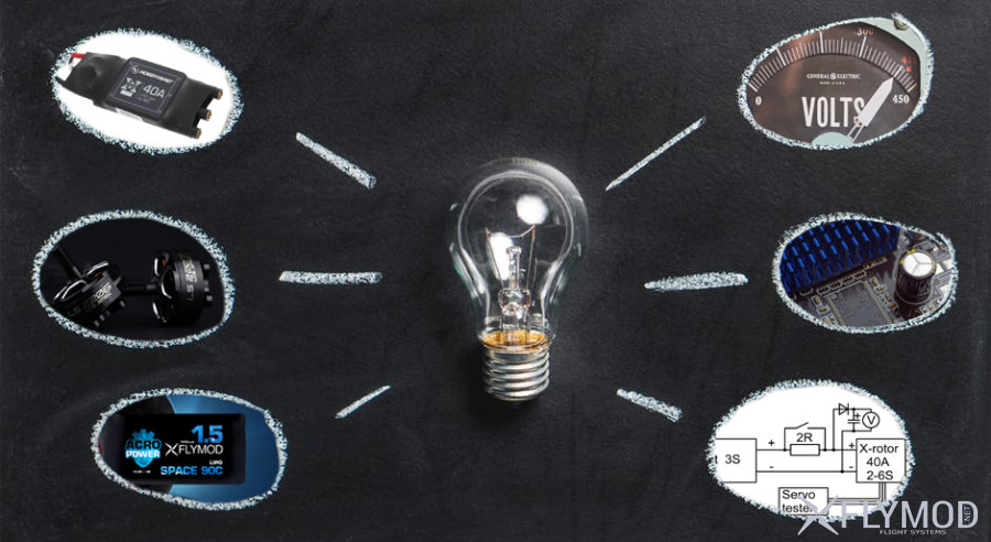
In this article we will talk about possible problems of assembling and setting up quadcopters when powering through a current limiter in the form of a light bulb, resistor or power supply from a laboratory power supply unit.
On the Internet, many people advise to make the first connection of the copter through a "light bulb", so as not to get a fire or "magic smoke" when short-circuiting if the installation is made inaccurately. As a result of using such a "safe trick", if there is an error in the circuit, the current will go through an additional resistance and its value will be limited to I = Upit/(Rdop+Rn), in case of a short circuit in the regulators power supply circuit, the maximum current will be I = Upit/Rdop.Indeed, it is better to make the first connection after a new assembly with such a "fuse", but often users, having made sure that nothing burned during the initial switch-on, continue to adjust the assembly, leaving this additional resistance connected.
There is no problem with checking the motors in this case, if you spin and stop them smoothly, but if you do it sharply, pulling the throttle to start working active braking, the motor turns into a generator, which begins to give energy back into the power circuit. When powered directly from the battery, this is not a problem, as its internal resistance is very low and it can absorb quite large currents without significantly increasing the voltage in the circuit. But when connected through a current limiter, the internal resistance of the power supply increases to the value of Rdop. The greater the resistance, the less current the battery will draw and the greater will be the emission voltage from the motors. The amplitude of the emission depends on the motor characteristics such as KV and power and how abruptly the motor is braked. Under hard braking, the voltage returned by the motors can be twice the voltage supplied to the regulators.
Thus, when powering through a current limiter or from a power supply unit, when braking sharply, the motors' energy is released into the copter's power circuit and the voltage can rise to such a level that the copter's circuit can fail and burn out regulators, power stabilizers, cameras, transmitters etc. This happens due to the breakdown of power switches or capacitors, for example, with a fairly powerful surge you can burn almost everything in the copter. To demonstrate the effect we have built a test bench according to the scheme below and recorded a video.
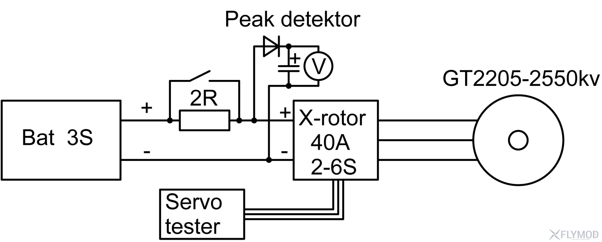
The test bench is powered by a 3S battery, which is connected to the regulator through a collection of resistors with a total resistance of 2 ohms. A switch is connected in parallel to the resistors, which can be used to apply power directly. A peak detector on a diode with a capacitor is added to the circuit to fix the amplitude of the surge, since the surge is quite short and it is impossible to see what the voltage was with an ordinary multimeter. It works as follows - when the voltage rises, the diode opens and charges the capacitor up to the maximum voltage, when the impulse drops, the diode closes and the capacitor remains charged, so the multimeter has time to fix the value of the peak.
In the test video we first connect the circuit directly to the battery, the switch is closed - the power goes directly. There are no voltage spikes when the motor speed changes smoothly, but there is a slight voltage spike when braking sharply. Then the switch is opened and power is supplied through a resistor. There are no emissions during smooth RPM changes, but during hard braking there is a power surge and the voltage rises above 20V+, relative to the original 12.4V. If our regulator was not designed to run on a 6S battery, it could have already failed. We can estimate how much power the surge was - the initial voltage was 12.4V - this is the battery voltage, the maximum surge voltage was 21.5V, we end up with a difference of about 9.1V. At the same time, the reverse current pulse through the resistor was at least 4.55A, which is already enough for failure of the copter circuit components. If we take into account that there are usually 4 motors on copters, the current will be even higher.
As a result, such a seemingly useful advice, how to save your iron when assembling sometimes helps to burn it on the contrary. Therefore, if you use current limiters, the motors should be turned only smoothly, do not make sudden changes in speed and do not touch the arm/disarm toggle switch at all. With the help of a light bulb, etc. you can make sure that there are no problems in the circuit, in the configurator smoothly spin the motors to check the soldering on the outputs of the regulators, if all the motors are spinning normally, then disconnect the light bulb, etc., and all the settings are carried out with a directly connected battery.
Also, this effect can burn electronics during sudden flips or drops on copters with very powerful motors, if you do not provide sufficiently reliable filtering of the power supply. In such cases, even with the battery directly connected, the energy release during braking is so large that the voltage rises to 20-30V even without additional resistance.
Use good quality LOW ESR capacitors in the regulators power supply circuitry to suppress ripple in flight and during drops.
Be careful when assembling and tuning.


Comments
Registration